Update: 2025 for NSX4.x
VMware NSX-T™ Data Center provides an agile software-defined infrastructure to build cloud-native application environments.
NSX-T Data Center focuses on providing networking, security, automation, and operational simplicity for emerging application frameworks and architectures that have heterogeneous endpoint environments and technology stacks. NSX-T Data Center supports cloud-native applications, bare metal workloads, multi-hypervisor environments, public clouds, and multiple clouds.
NSX-T Data Center is designed for management, operation, and consumption by development organizations. NSX-T Data Center allows IT teams and development teams to select the technologies best suited for their applications.
In the following entry we will describe the default configuration of NSX-T following the same basic principles (configuration) used in the VMware Cloud Foundation (VCF) deployment, but manually.
Step 1: Overview of Example
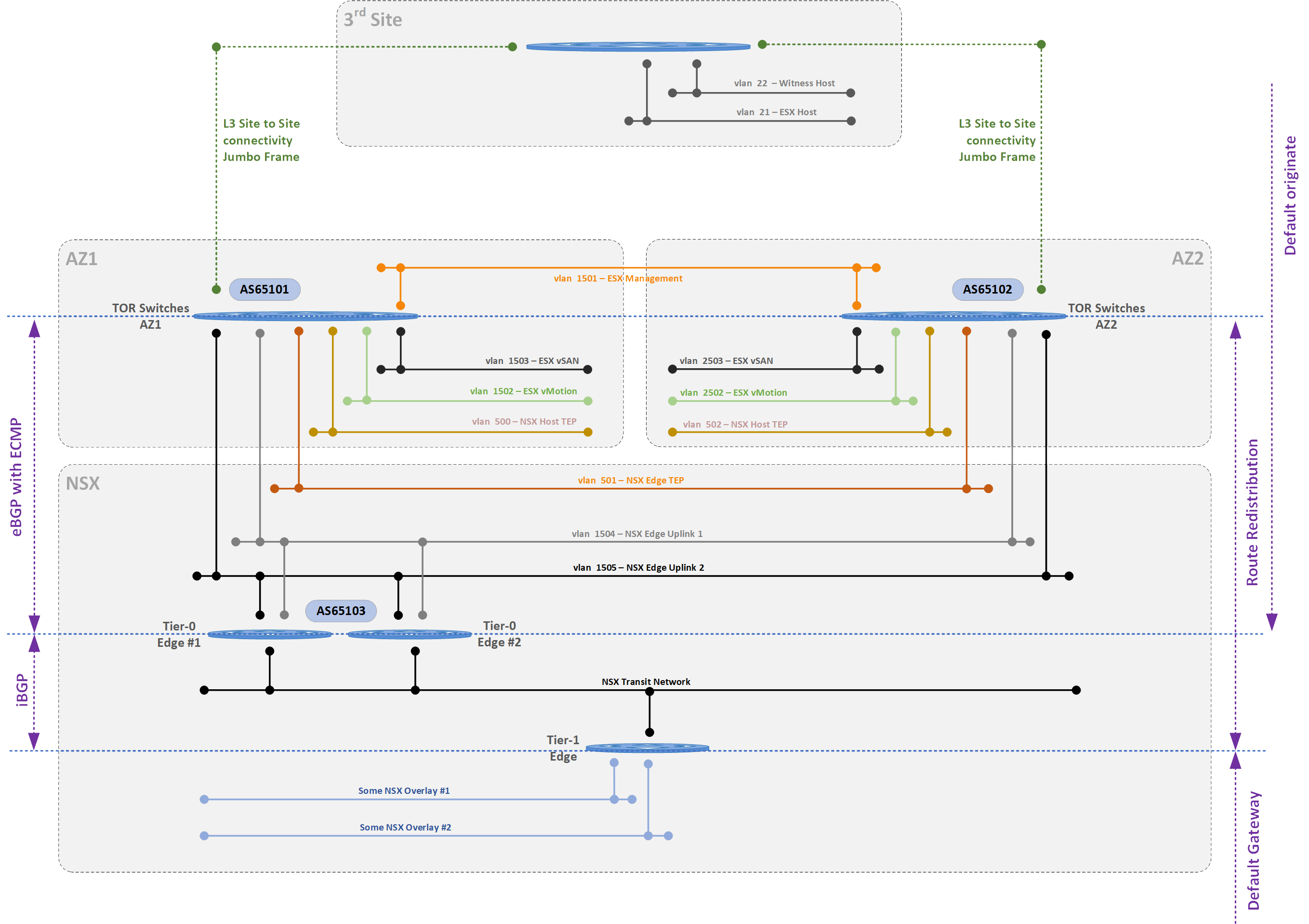
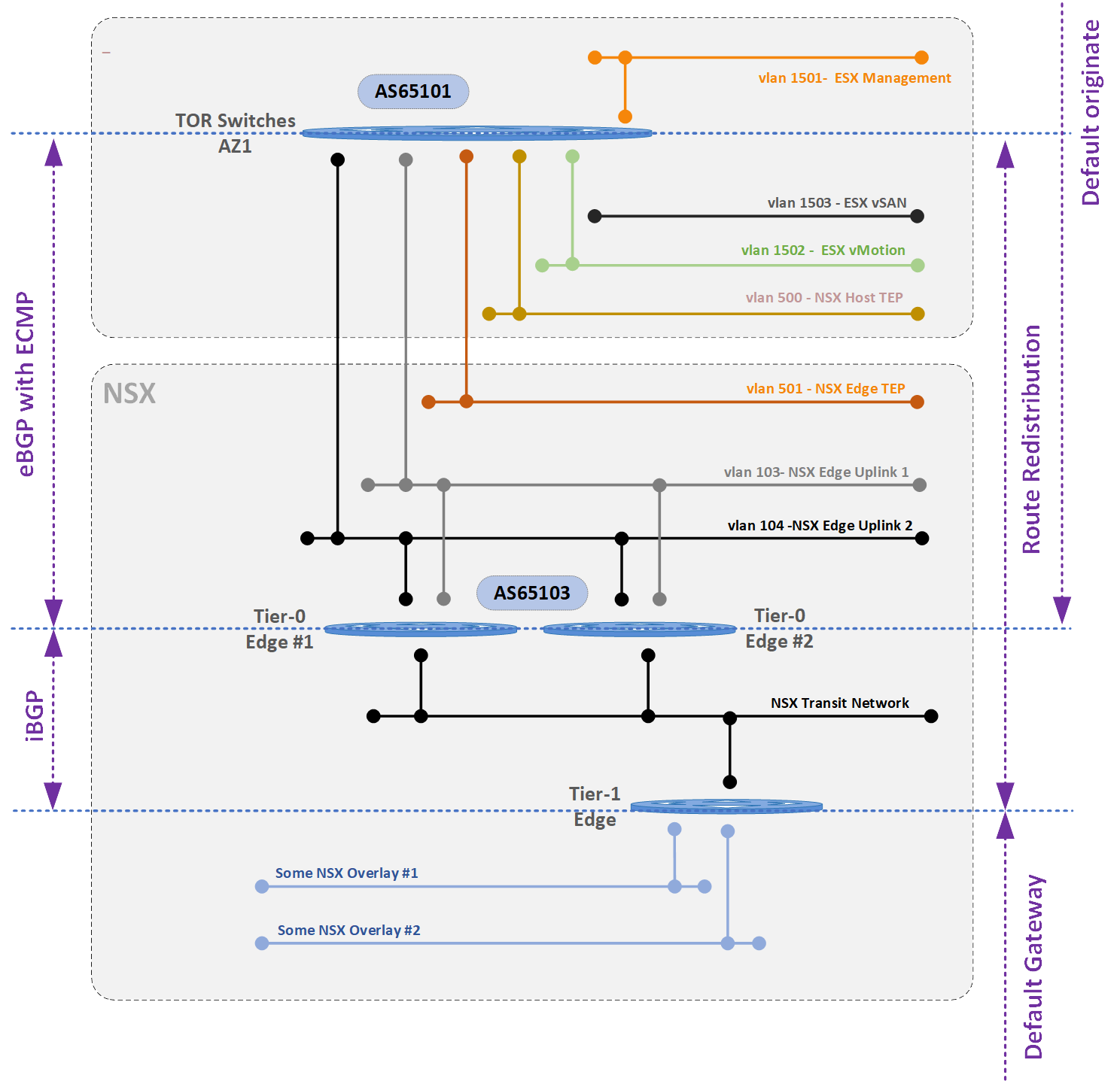
Below diagram an example of the configuration in a stretched cluster or local cluster. The following blog entry will primarily focus on the configuration of NSX-T on a local cluster.
Some major pointers are:
- The NSX-T EDGE TEP’s must be in a seperate VLAN than the Host TEP Networks. These must be routable to each other (same VRF)
- In the following example the NSX-T edges fail-over from one site to another (this is normally the use case for the VCF Management Domain). However it is possible to deploy dedicated NSX-T edges for N/S traffic on each site and have them dedicated there. Would change the below configuration to deploy four edges instead of two, having the VTEP network for the edges as non-stretched and having dedicated BGP peers on each site. Consult your VMware/NSX architect for more information.
Stretched Cluster Overview
Local Cluster Overview
Step 2: Profile – Host Uplink
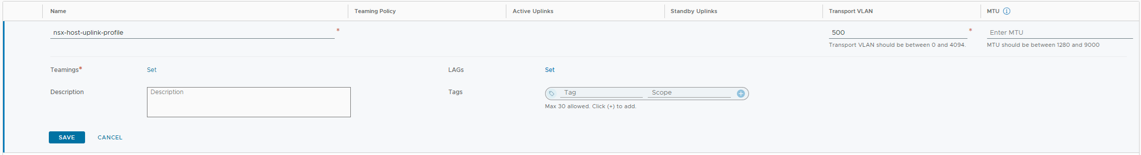
One of the first things to define is the host uplink profile to be used for the ESXi hosts in the NSX-T cluster. Normally speaking two links will be used in this profile, but these two links will provide two functionalities:
- Overlay Configuration : active-active (Load Balance Source)
- Uplink for BGP Peering : one active link only (Failover order)
Also define the Transport VLAN (500) for this cluster as the NSX-T Overlay network. Do not define an MTU.
In the NSX-T Manager in the menu select – System > Fabric > Profiles > Uplink Profiles
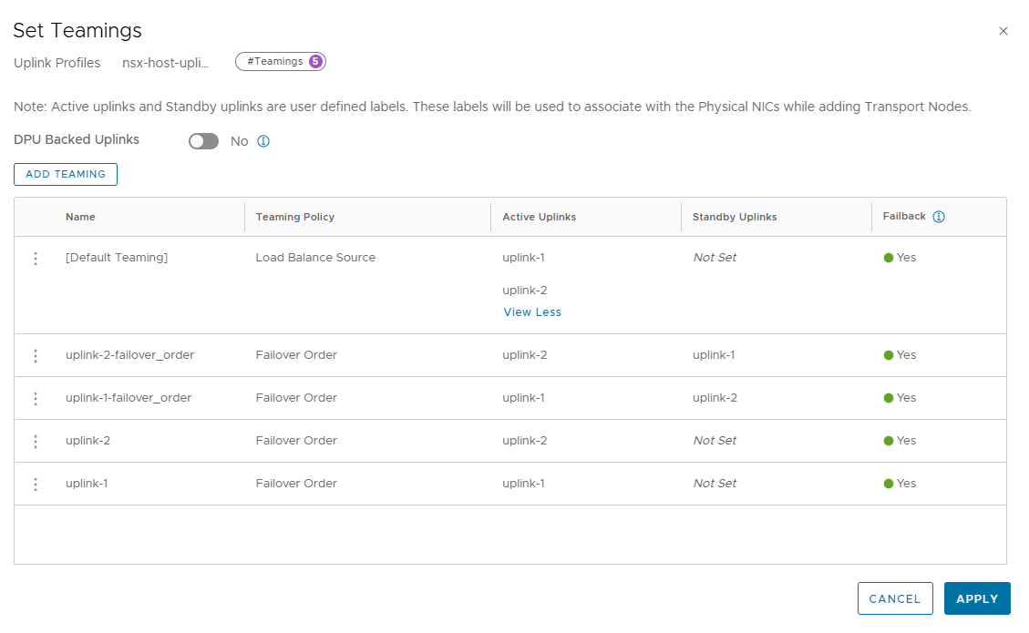
In the teaming section add the following teaming combinations:
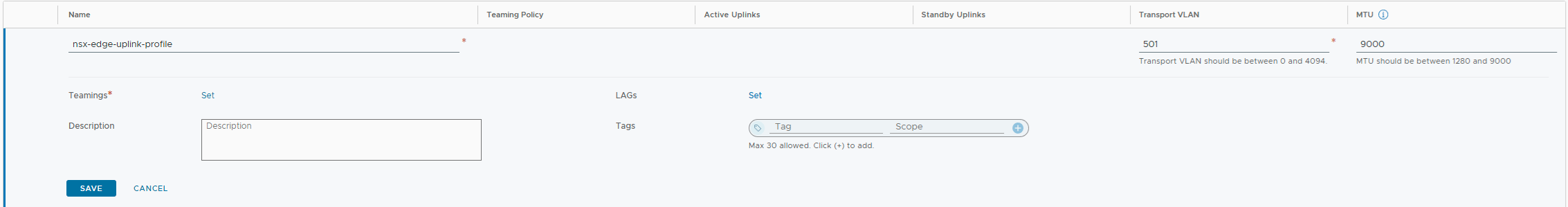
Step 3: Profile – Edge Uplink
Define the NSX-T edge uplink profile to be used for in the NSX-T cluster.
- Overlay Configuration : active-active (Load Balance Source)
- Uplink for BGP Peering : one active link only (Failover order)
Also define the Transport VLAN (501) for this cluster as the NSX-T Overlay network.
Also define a default MTU size to use, this is the MTU that will be used for all traffic including North-South.
In the NSX-T Manager in the menu select – System > Fabric > Profiles > Uplink Profiles
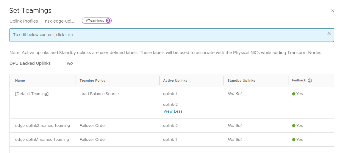
In the teaming section add the following teaming combinations:
Step 4: Transport Zones
Create two transport zones, one for the ESXi hosts in the cluster, the other for the edge uplinks
The two [default] transport zones can be used: Overay and Edge
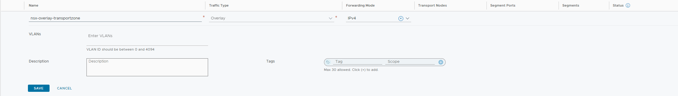
In the NSX-T Manager in the menu select – System > Fabric > Transport Zones
NSX-T Host Overlay Transport Zone
The NSX-T Host (ESX) Host Overlay transport zone, is an overlay defined network.
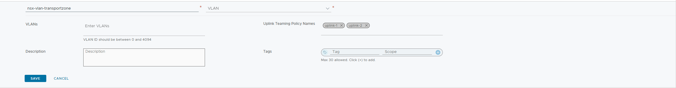
NSX-T Edge VLAN (Uplink) Transport Zone
The NSX-T Host (ESX) Host Overlay transport zone, is a VLAN defined network.
Step 5: Profile – Transport Node
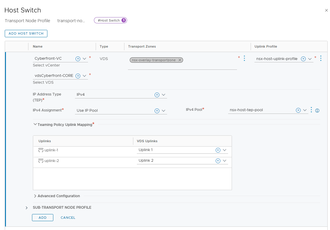
A transport node profile is a template to define configuration that is applied to a cluster. It is not applied to prepare standalone hosts. Prepare vCenter Server cluster hosts as transport nodes by applying a transport node profile. Transport node profiles define transport zones, member hosts, N-VDS switch configuration including uplink profile, IP assignment, mapping of physical NICs to uplink virtual interfaces and so on.
In the NSX-T Manager in the menu select – System > Fabric > Profiles > Transport Node Profiles
Create a new transport node profile

Add a host switch to configuration:
Step 6: Configure ESXi host
Select your ESXi cluster and attach the appropriate Transport Edge Node profile to the cluster. This action will install the NSX VIB’s and properly configure each host in the tranport overlay network and uplinks.
In the NSX-T Manager in the menu select – System > Fabric > Nodes > Host Transport Nodes
Select the appropriate vCenter and vSphere Cluster. In the Tab select ‘Configure NSX‘ and select the appropriate Node Profile to attach.
Step 7: Edge VDS Port Groups
In the example we will deploy two medium sized NSX-T edges. First make sure that the VDS also has two port groups defined for the uplink configuration of the NSX-T Edges, as follows:
NSX-Uplink-LINK1
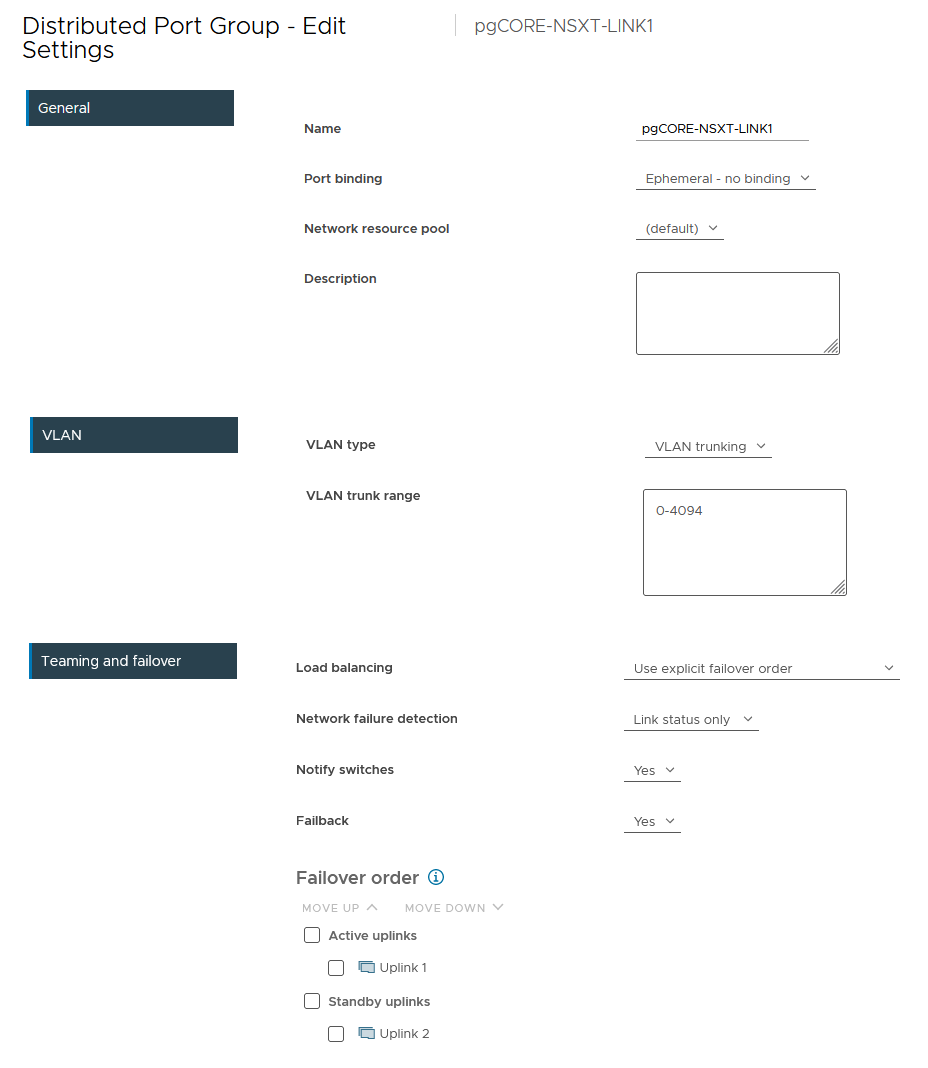
NSX-Uplink-LINK2

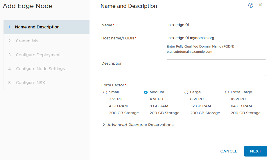
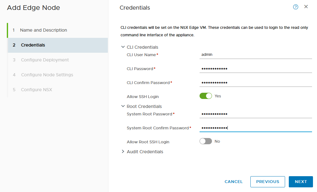
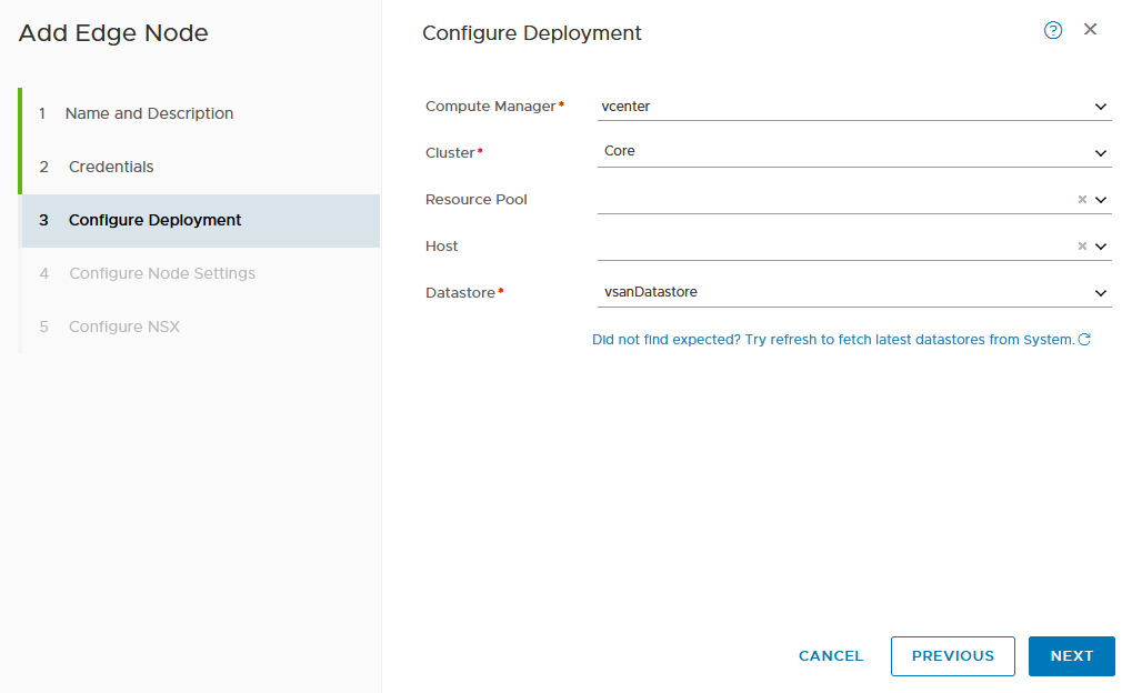
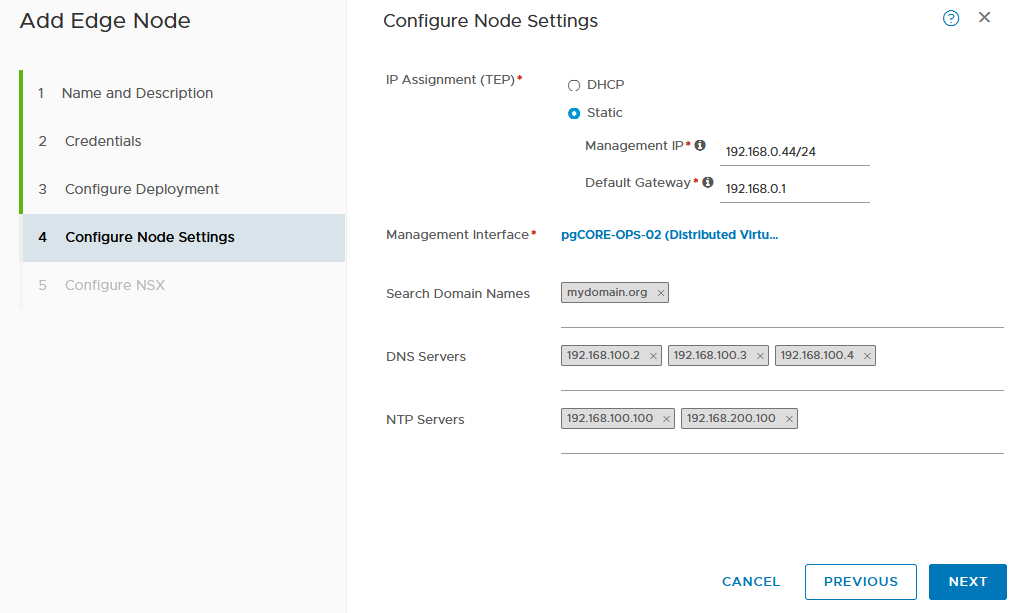
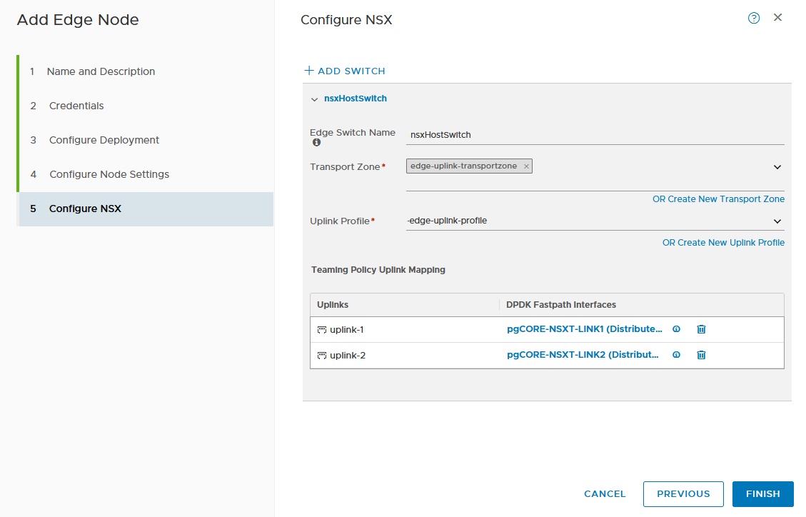
Step 8: Deploy NSX-T Edge(s)
To create the edges, in the NSX-T Manager in the menu select – System > Fabric > Nodes > Edge Transport Nodes click on ‘Add Edge Node‘
- Always use static IP addressed for your NSX-T edge VTEP’s (recommendation)
- Make sure to select the appropriate ‘Form Factor’, it is not possible to resize later!
Perform this action twice, for each NSX-T Edge.
Step 9: Create NSX-T Edge Cluster
In the NSX-T Manager in the menu select – System > Fabric > Nodes > Edge Cluster click on ‘Add Edge Cluster‘. Add both newly created NSX-T edges to this cluster.
Step 10: Create BGP VLANs
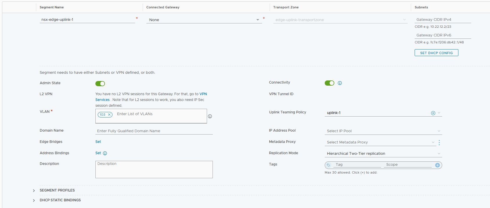
For each of the NSX-T edges we will have to create two segments, one for each of the BGP peering(s). In the NSX-T Manager in the menu select – Networking > Segments click on ‘Add Segment.
NSX Segement : Edge Uplink #1
- Edge Uplink Transport Zone
- This is the segment which will be used for the first BGP Peering network (VLAN 103)
- uplink-1 as the interface
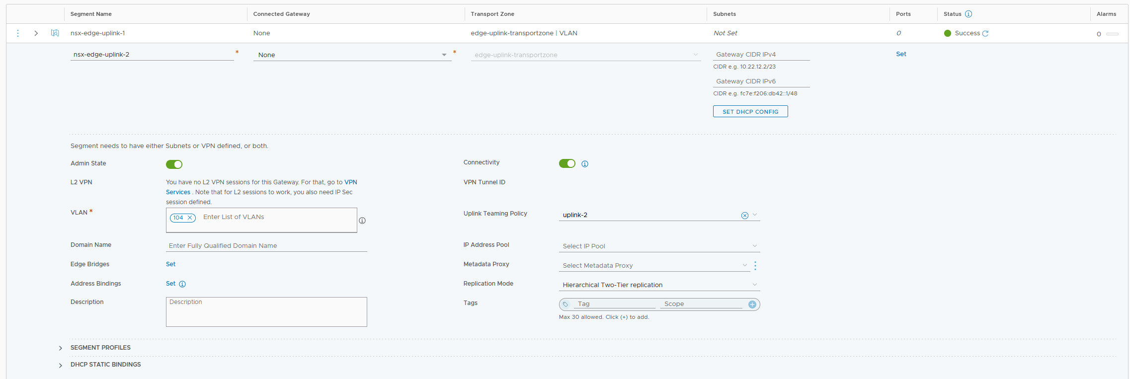
NSX Segement : Edge Uplink #2
- Edge Uplink Transport Zone
- This is the segment which will be used for the second BGP Peering network (VLAN 104)
- uplink-2 as the interface
Step 11: Define T0
<todo>
Step 12: Define T1
<todo>
Step 13: Define T0 BGP Peers
<todo>